Many of the tech articles on this site does relate to true bypass in one way or another. But there are also other wiring schemes that can come in handy. For instance, if you want to set up two pedals (or groups of pedals) and alternate between them, you’d need something more than a single true bypass loop. You could use a dual true bypass loop box, connect the pedals/groups to the two loops and hit both to alternate between them. But due to Murphy’s Law, you will eventually end up on stage, right before the big solo, with both loops off… some things are simply inevitable 😉
This is where the A/B looper comes in. While technically not part of the true bypass family – the same way a regular A/B box isn’t true bypass either – it can be very useful. In essence, it is an A/B switch with an added switch pole for the returns.
The basic diagram looks like this:
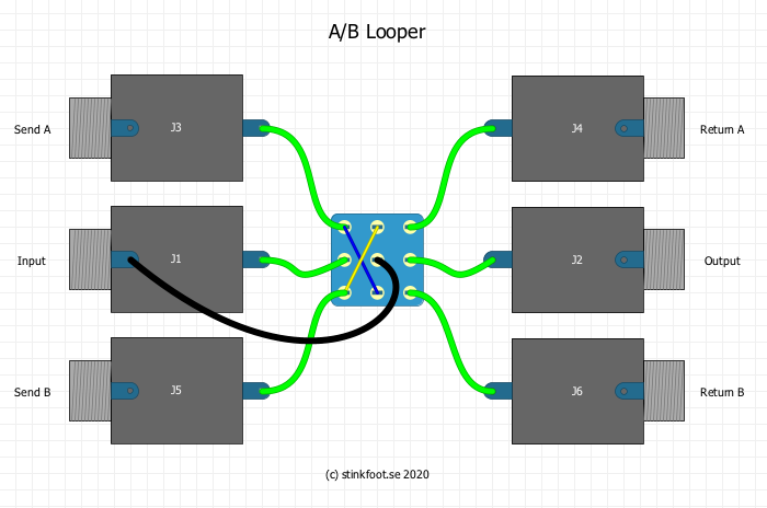
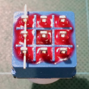
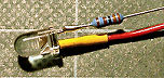
The switch is a 3PDT, oriented in north-south fashion (where the rows of lugs line up top to bottom, as in the pic to the right). The left group of jacks and the left/middle rows on the switch actually constitute an A/B switching scheme, which handles the signal going to the two pedals/groups. The ground wire from the center lug will mute the input of unused pedal/group, to keep things quiet. The jacks on the right and the third/right row on the switch then simply handles the signal returns.
Can I get an LED with that?
Of course 🙂 But since we’re already using all three rows on the 3PDT, we need a bigger switch. Enter the 4PDT… It works the same as an SPDT, DPDT and 3PDT, but with four rows of lugs, which we will use to turn a pair of LED’s on/off.
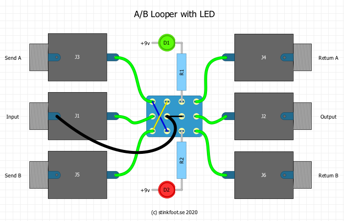
In this example, we have a common 9v+ going to the LED anodes (long leg), with the cathodes (short leg/flat side) towards the switch and, eventually, ground. Why two separate resistors, you might ask? I have found that even LED’s of the same type and size will vary their brightness with the colour. Having separate resistors will let you tweak their brightness individually.
If you still want to have just one resistor, you can place it on the switch, in place of the jumper from row 2/middle to row 3/middle, as below:
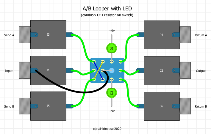
This will make for a slightly neater wiring, but again – you won’t be able to tailor the brightness to the individual LED’s. I usually cut the cathode (short leg/flat side) leg short, and use the resistor to reach the switch, so I’d go for separate resistors over the slightly neater wiring with a single resistor any day. But I thought I’d include the digram anyway,
But what if I want to turn both pedals off?
Well, you could of course switch one of the pedals to bypass, and make sure to switch to that loop when you want to play without either pedal. But since Murphy’s Law still applies – anything that can go wrong, will eventually do so – we can do better than that.
Simply add another switch, to add a true bypass wiring around the whole thing. You may want to use a bigger box for the build, to get sufficient spacing between the switches. But other than that, it’s quite simple. Wiring diagrams can be found here (scroll down to ”better true bypass” or ”true bypass with LED”). Wire the input and output jacks to the ”input” and ”output” on the true bypass switch, with the ”send” and ”return” to the A/B switch where the jacks used to go. That’s it! The basic diagram looks like this:
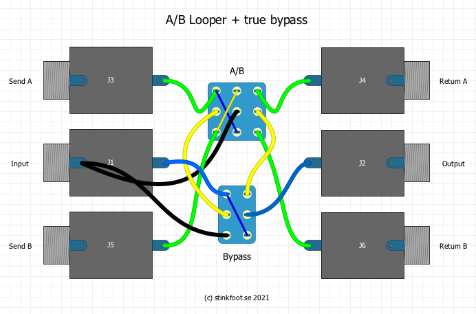
Input/output wires are blue, with the send/return to the A/B section in yellow. Each switch gets a ground wire (black) to the input jack sleeve connection. So far, so good. But… if you want LED’s with that, things get a little more complicated. However, once again, it’s simply a matter of extending the two switches to accommodate the LED’s – the audio portion stays the same. So here goes:
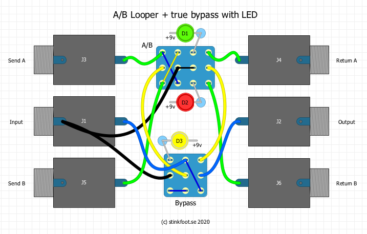
I had to make the resistors smaller in the diagram, to fit it all in, but they are there (the light blue things between the LED and switch). And the principle for those is the same as before: a common +9v feed for all LED anodes, with a resistor from the cathode (short leg/flat side) to the switch, where it eventually ends up at ground to turn the LED on.
I don’t want to build my own – where can I buy one?
Yes. Most places that do true bypass loop boxes and A/B boxes etc will have this type of box in their repertoire as well. Also, I’d be remiss if I didn’t mention the humble Boss LS-2 Line Selector – it can do both A/B and A/B/Bypass switching for you, among a whole host of other things. You can read more about the LS-2 here.