There has been lots of discussion about exactly how Voodoo Lab can call their pedals true bypass, when they only use a DPDT switch and still manages to switch an LED too. They could have used the ”Millenium” style of bypass, where the unused (in bypass mode) circuit output is used to control a FET transistor that turns the LED off. But they didn’t… The switch in the pedal actually only switches the output, and yet, I’d agree to call it true bypass. Confused? So was I…
First impressions

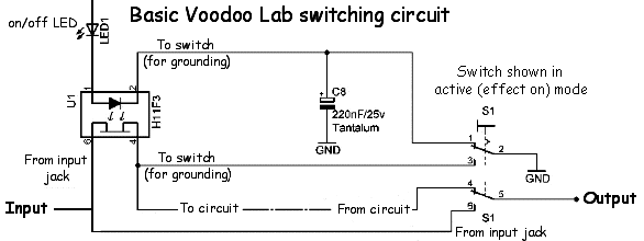
When I cracked open my four-knob Tremolo to check it out, I found that the switch actually only switches the output – the same way as many other non-true bypass (hardwire) pedals (MXR/Dunlop for instance). The input signal is split right at the input jack, where one trace (on the component side of the pcb) leads straight to the switch, while another trace (on the rear side of the pcb) leads straight to the input of an optocoupler unit, whose control voltage side sits in the path of the LED. From there, the signal is then fed into the actual circuit.
Opto…what?
Basically, an optocoupler acts as an on/off switch that is controlled by a tiny LED inside the unit. It has two sides – one hooked up to the internal LED (also known as the ”control voltage” side), and the other side functioning as the switch. When the internal LED lights up, the switch on the other side of the optocoupler opens. Now, the control voltage side is connected in series with the indicator LED, so when the indicator LED is lit (which is controlled by the main switch, which at the same time switches the output jack over to the circuit output), so is the one in the optocoupler. This means that when the pedal is active, the circuit input is connected to the input jack (via the optocoupler). When you turn the pedal off, both LEDs turn off, and the optocoupler shuts down any connection between input jack and the circuit input. At the same time, the ground connection through the main switch, which was previously used to complete the LED circuit, is now connected to the circuit input (after the optocoupler, but before the actual input stage), to mute the effect input. It’s quite ingenious, and it really works.
Schematic
Here’s a circuit diagram over how it works. I’ve removed the current limiting resistor from the 9v+ supply to the indicator LED, to make the schematic a little more manageable in size. I’ve also removed the actual circuit (represented here by the dashed line).

What this all means is that while the pedal isn’t true bypass in the most strict sense of the word – after all, the optocoupler is part of the circuit – in practice, its function is exactly the same as if it had had true bypass the ”normal” way. In bypass mode, the optocoupler effectively stops the circuit from connecting to the bypass line – remember the grounding? If the circuit had been still hanging on to the bypass line, the pedal would be muted in bypass… I’m also impressed by how the designers at Voodoo Lab took the problems with hard-wired/output only switching systems seriously, and took the time to work out a true bypass solution that actually works, without having to buy the more expensive and potentially more fragile 3PDT switches.