With my pedalboards, I normally just connect the guitar to the first pedal, and go from the output of the last pedal to the amp. Some boards have patch bays, which let you plug the guitar and amp cables into, with additional cables running to and from the first and last pedal. But when running all pedals in line, in front of the amp, I don’t really see the point. It’s just one more thing to go wrong. Also, I want the guitar cable to enter the board on the right side (to avoid tripping over it), and the amp cable to exit on the left (for the same reason).
However, when I started using the distortion channel on the Marshall, I started thinking about ways to move certain effects to the amp’s effects loop, without having to rip up patch cables every time I wanted to use that amp for a gig. So I started drawing up plans for a connection box.
In its purest form, this is simply a box with three jacks on either side. Each jack has a partner on the other side, so the connections made on the outside has a duplicate jack on the other side, where the appropriate pedal connections are made.
The jacks on the outside and their inboard partners are:
- To amp input <- from last pedal in the in-front chain
- From fx loop send -> to first pedal in the fx loop chain
- To fx loop return <- from last pedal in the fx loop chain
I didn’t include the guitar cable input in this box, as that’d inevitably mean you’d have to do some awkward cable routing. This way, the guitar cable stays on the right side, while all cables associated with the amp goes to the left (or out the back of the board, depending on where you place the box).
Specifications and parts
On top of the most simple design brief mentioned above, I did add a couple of features to this design.
- All jacks except the first one (from last pedal in the in-front chain, on the pedalboard side – J4 in the drawing) should be isolated from the box, to avoid connecting the ground planes for the pedals running in front of the amp with that of those running in the amp’s fx loop. That can cause hum. Btw, this means you also need a power supply with isolated outputs, to keep the two groups of pedals separated. Or at least separate power supplies for the two groups.
- Using switching jacks means you can easily run all pedals in a single chain (in front of the amp), without having to re-connect anything on the pedalboard side. If you don’t do this, you can of course add a patch cable on the outgoing side to run the whole chain in-line.
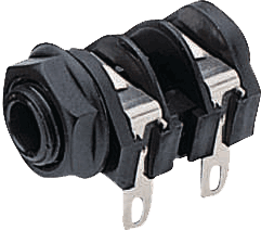
I suggest you use Cliff CL1160A or REAN NYS2122 jacks, which are both isolated and allow for switching. The legs visible in the pic connect to the plug’s sleeve and tip. On the other side, there are two additional legs which connect to their counterparts on the first side only when the plug is removed from the jack. This means you can use the switching legs to make the ”to amp input” jack connect to the ”from fx loop send” when those jacks are left empty. That way, you can use the whole board in-line, by using the ”to fx loop return” jack as the main output.
If you use the type of jack pictured, where the nut is nylon as well as the ”neck” of the jack, I’d suggest a dab of threadlock (Loctite blue works great, but really any threadlock will work), to stop the nuts from undoing themselves. I learned that the hard way 🙂
Remember that the first jack (from the end of the in-front chain) need to be grounded to the box, as mentioned earlier. You can accomplish this by simply using a jack that isn’t isolated, or you can run a wire from the sleeve tab on this jack to the box (you can just squeeze it between the jack’s body and the box if you like).
Schematic
Here’s the schematic drawing:
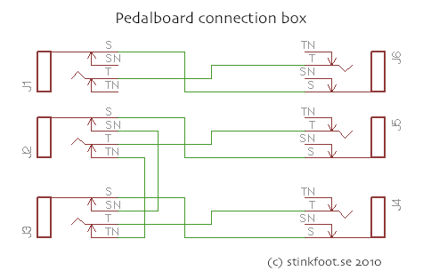
S and T are the main connectors for the sleeve and tip, respectively, while SN and TN are the switching tabs on the other side. In this drawing, J1/J6 are the ”to fx loop return” jacks, J2/J5 are ”from fx loop send” while J3/J4 are the ”to amp input” jacks. I drew it this way because on the pedalboard it was intended for, the fx loop pedals mostly sat in the upper/back row, while the in front pedals were mostly grouped along the lower edge of the board. This meant I preferred positioning the box along the left side of the board, with the plugs for the outboard connections coming in from the left. You can of course place the jacks however you like them, as long as you keep track of which is which 🙂
Building the box
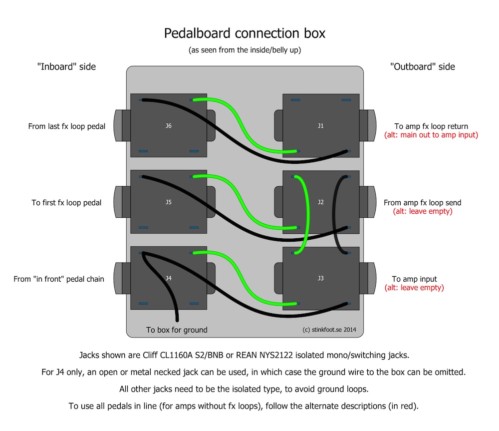
The jacks fit nicely into a Hammond 1590B (or similar) box, with three jacks on each side. I’ll continue this article when/if I start building… In the mean time, I made up a drawing that some of you might find easier to follow than the raw schematic. This drawing shows the box as seen from the inside (flipped over) with the jacks installed so the solder lugs face up towards you. With this layout, the box is perfect for a position along the left side of the board.
A different layout
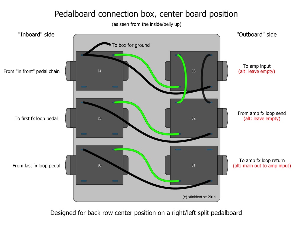
Again, the box as drawn above is designed to sit on the left side of a pedalboard where the ”in front” pedals mainly live on the lower/front row and the ”fx loop” pedals in the back row. You can of course fit the jacks in a different manner, if your pedalboard layout is different. I recently built one of these for a board where the board was divided more down the middle (”in front” pedals grouped more to the right and ”fx loop” pedals grouped more to the left). With that board, the box needed to sit in the middle of the board, with the outboard jacks facing out. To avoid having to cross the patch cables, and (more importantly) to make the outboard connections better match the physical layout of the pedals, I put J4/J3 at the top, and J6/J1 at the bottom. As long as you keep the wiring intact (especially the connections between J3 and J2, which still has to use the same lugs), it will work just fine. But just to be sure, here’s a revised drawing for this layout:
Finished…

Here’s a photo of a wired up ”center position” box (click for full size). When mounted on a pedalboard, the jacks to the right will be facing outwards, providing the connections to the amp, while those to the left are the ”inboard” ones.
Note the black wire from J4 that goes to ground – it is simply soldered to a metal washer, held in place by the jack itself. A proper crimped ring connector would have been neater, but since I didn’t have one handy, this had to do. You can of course also use a metal-necked jack for J4, and get the ground connection built in.
Also, as you can see, the solder tabs on the jacks are bent down a bit – this is simply done to stop them shorting out on the bottom plate 🙂