There are plenty of wiring schemes for true bypass floating around out there, and of course there are a few on these pages as well. But they do differ somewhat – sometimes it’s because a different wiring style is being used, and other times it’s because a specific pedal needs a specific wiring style. I will also sometimes move stuff around to fit a specific pedal (for instance if moving the ground connection over to the other side would make for an easier installation). Of course, all this can get confusing, even if you’re only prowling this site for info, and since I started getting requests for diagrams of the basic true bypass wiring styles, I decided to make a page just for that. But before we dive into the wirings, let’s take a look at the humble switches we’ll be using.
The switch
For basic true bypass wiring, you’ll need a DPDT (double pole, double throw) switch. It is basically two SPDT (single pole, double throw) switches side by side. Later, we’ll also delve into the 3PDT (yep, triple pole, double throw) switches, which of course are three SPDT switches operated in unison.
These switches all are the latching type (on/on), and work by connecting the pole (center lug, 2 or 5 in the pic) to either of the throws (outer lugs, 1/3 or 4/6 in the pic). As you click the switch, the connection changes, so if you had 1-2 and 4-5 connected, the new connections will be 2-3 and 5-6.
Basic true bypass
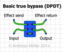
This is the true bypass wiring in its most basic form. Armed with the knowledge you just learned, we can see that the signal enters and leaves the switch on the poles (middle lugs). The switch will then either let the signal just jump over to the output side and on to the output jack (bypass), or pass through the effect circuit before being sent to the output jack (active).
Better true bypass
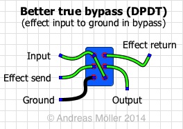
The basic wiring is not without drawbacks. The biggest one is that when you go to bypass mode, the circuit input is simply disconnected, left hanging like when you accidentally unplug the guitar cable. This can create a ”thump” or ”pop” when you click the switch to turn the effect on. Adding a pulldown resistor to the input of the circuit can help (it pulls the input down towards ground when disconnected), and some circuits already have those. But you can also combat this by simply changing the wiring style somewhat. This wiring shorts the circuit input to ground in bypass. Compared to unplugging the guitar cable (as mentioned earlier), this is more like turning the guitar volume off. And this is why I always use the input grounding wiring style 🙂
True bypass with LED
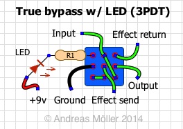
Up to this point, we’ve used DPDT (double pole, double throw) switches for our wirings. If you want to also have an on/off LED, you need to add a third row of lugs (a third pole with two throws) to do that. So here it is! It’s basically the ”better true bypass” wiring above, but with an additional jumper to use the ground connection both for muting the circuit input (in bypass) and completing the circuit for the LED (in active).
R1 is the current limiting resistor for the LED. I use as big a resistor as I can get away with, both to limit the current draw (save battery) and the risk of switch ”thumps”. To do that, obviously the brighter the LED, the better. I use ultra-bright LED’s (in the 8.000-10.000 mcd range), with resistors ranging from 4.7K to 8.2K. That way I’ll get plenty of brightness with minimal current draw.
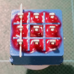
While the DPDT switches are easy to orient to match the wiring diagrams (since they have two rows of three lugs), the 3PDT is different. Since it is symmetrical (3×3 lugs), it is possible to accidentally turn it 90 degrees off, meaning the wiring won’t work at all. All my 3PDT wiring diagrams assume that the switch is oriented with the holes in the lugs lining up north/south. The pic to the right shows the real thing in that orientation. The piece of wire through the leftmost row of lugs is there only for illustration – if you can feed a wire through the same way, you know your switch is oriented the right way in relation to the diagrams on this page.
And yes, the 3PDT wiring diagram found on the Crybaby wah LED page doesn’t fully match the one on this page. This is because for the Crybaby, I had to separate the signal ground from the ground/negative for the LED, to stop a ”thump” noise when the pedal is turned on/off. For most other pedals, I haven’t had the need to do so, which is why the general 3PDT wiring found on this page has a single ground wire.