As mentioned on the ”Changing the tone of the GCB-95 Crybaby” page, you can change the standard CGB-95 into a bass wah or Zakk Wylde (ZW-45) or Hendrix wah (JH-1) by simply replacing a capacitor. But with only a few more parts and a little drilling, you could install a switch to choose between different capacitor values on the fly. Here we will focus on getting three sounds: stock GCB-95, JH-1/ZW-45 and bass wah. But you could easily use this layout to choose any capacitor values you like. For instance, on my personal wah, I might be more inclined to choose values that are fairly close, so I can use the switch to fine-tune the tone (rather than go as far as move it into the bass region). But it’s all up to you!
Capacitor theory
But first, let’s cover the basics of capacitors. Their value is usually written out in microfarads (µF) or as a code consisting of two digits with a third to show the number of zeroes to add, to form a number in picofarads (pF). The stock capacitor we’re talking about there is 0.01µF, which is the same as 10 000pF (the code for which would be 103 = 10 + 3 zeroes). 0.068µF would read as 683 in code form, while 0.022µF is – you guessed it – 223.
For this mod, though, we will not replace the stock capacitor. Rather, we will add capacitors to that one to form the desired values. Luckily, when added in parallel (on top of each other), capacitors simply add their values together. So if you were to add another 0.01µF/103 cap on top of the existing one, you’d end up with 0.02µF as the total value, which is close enough for these purposes. If you were to find a 0.012µF cap, you’d get to the full 0.022µF, but that value is quite hard to find. Similarly, adding a 0.056µF cap (another quite common value) to the existing 0.01µF, you’d end up with 0.066µF, which is close enough for the bass wah setting.
The switch and wiring
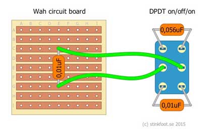
Since there’s plenty of room in the wah shell, we can get away with using a slightly larger switch and solder the capacitors straight to it, for a neater look. We will be using a three-position DPDT on/off/on switch, where the middle position leaves the switch open.
The simplest way is to simply solder the two wires from the switch to where the stock capacitor was on the circuit board. In the middle position, you have the stock wah sound, while the two outer positions provide ZW-45/JH-1 and bass wah sounds, respectively. Film capacitors are non-polarized (they do not have a + and – side), so it does not matter which way you turn them or which way you solder the wires (as long as they are on separate sides of the capacitor, of course).
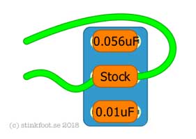
While soldering wires directly to the capacitor on the board works just fine, it does look a little untidy. If you are like me, and prefer a cleaner/neater look, move the stock capacitor to the switch, and just have the wires go where the stock capacitor was on the circuit board. Even though it means I have to take the circuit board out, I prefer doing it this way. I suppose I am a neat freak 🙂
Doing the mod
First, you need to source the parts:
- Film capacitors (0.01µF and 0.056µF for this mod)
- DPDT on/off/on switch
- Hookup wire
Time to drill the case. But before you do any drilling, you need to decide where to drill. Remember to check for clearance inside, so you’re sure the switch + components will fit. You will also need to take the battery compartment into account… it’s easy to forget that the battery will use that space when the pedal is back together again 🙂 Also, make sure you don’t fit the switch where it might interfere with the cables. The natural position would be to fit it above the circuit board, to the left of the wah pot. You could also fit it low, where the wah shell is a little slimmer and the switch won’t get in the way of the cables. But if your pedal is the type that has the battery compartment in the back plate, the switch needs to go really low, just above the point where the feet screws in. Do not be tempted use the prepared punchouts for LED’s up by the footswitch! It looks tempting to have the switch there, since it would be pointing up (the same way the footswitch does) and not protrude from the side of the wah. But in that position, the switch will interfere with the wah treadle…
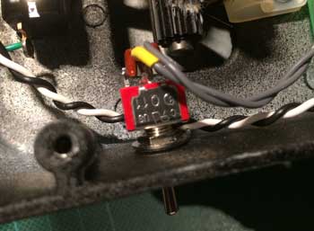
With all that said, once you’ve decided where to drill, have at it. Punch first, and keep the wah shell angled so you’re drilling at a straight angle to the surface. The pic to the right shows a switch installed in the upper section of the wah, near the pot (and here I also used an SPDT rather than a DPDT, but more on that later).
Prepare the switch by soldering the capacitors and wires, then fit it to the shell. I prefer doing as much of the solder work outside of the box, where I can rotate the switch as I like. But you could also fit the switch first, then solder it up – there’s plenty of room, after all.
Finally, if you decided to keep the stock capacitor in place, solder the two wires to the capacitor on the board. You can do it the quick/dirty way, by simply tacking the wires (you did remember to tin them, right?) to the capacitor legs. Then you won’t even have to remove the circuit board from the shell.
If you moved the stock capacitor to the switch, simply run the two wires to the points on the circuit board where the capacitor used to sit. In either case, make sure the wires can’t get stuck in the gear mechanism to the main pot – that could get ugly very quickly.
Variants and tweaks
Alternative values – as I already mentioned, if I were to do this mod to my wah, I’d probably go for different capacitor values. Using a 0.0047µF (472) and a 0.01µF (103) would give me the stock sound, the JH-1 sound and a setting in between the two, which would be more useful to me than the bass setting.
More options – you could use a six-way rotary switch, which would give you six different capacitors to choose from. Make the stock 0.01µF one of those six, and just have the two wires from the switch replacing the stock capacitor on the board. Since you’re not adding capacitors in parallel, choose the actual values you want. Personally, I’d go for something like 0.0082µF, 0.01µF, 0.012µF, 0.015µF and so on, for a really fine tune-able wah. Roger Mayer did this ages ago in a wah that sounds great! One caveat, though – like most owners of that wah did, you might find yourself choosing one of the settings and using that one all the time, in which case you could just as well have skipped all of this and simply installed that value capacitor right on the circuit board… But such are the joys of modding 😀
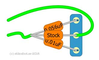
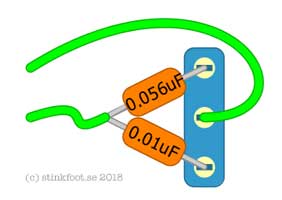
Using an SPDT – I recently did the three-way mod to a wah, and only had an SPDT (single row of lugs) on/off/on available. I did have a few on/on DPDT switches, but since I wanted the three different sounds, I decided to use the SPDT instead. To make this work, I tied one end of the three capacitors together, and soldered them to a wire. The other ends went to the three lugs on the switch, with the second wire coming from the center lug. The two wires then went into the two holes on the circuit board.
Using an on/on switch – if you can’t find an on/off/on switch, you will only get two different sounds. You can still wire it the way I described above, but with the capacitor values described above, your only two choices will be the JH-1 and Bass settings. If you’d rather have the stock setting and another alternate sound, just wire up one side of the switch (0.056µF for bass, 0.01µF for JH-1) and leave the other one open. Note that this wiring method relies on the stock capacitor staying in place on the circuit board,
If you’d rather remove the stock capacitor from the board, which is a much neater wiring style, you can simply choose the values you want the two settings to be for the two outer positions (0.01µF stock, 0.022µF for JH-1, 0.068µF for bass wah).
The pic shows that wiring with an SPDT switch, but it’d work the same with a DPDT on/on, using the wiring style shown earlier.