Also known as ”circuit mods”. This is a collection of changes you can make to the Crybaby circuit, to change its tone and response. Please note that this is not a list of my suggestions – in other words, I’m not suggesting you do all of the mods listed here. Some of them may not work well together, or may overlap each other. This is simply a list of things that can be done. My own ”recipe” is posted on a different page 🙂
Simple range adjustment
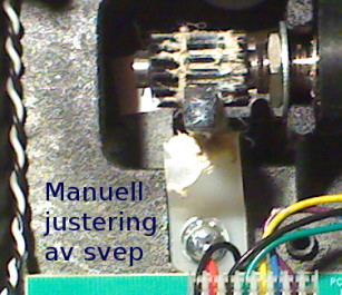
This can help tame some of the shrill highs at the toe end of the travel. Doing this mod requires no soldering skills at all, and I regularly do it to many of the wahs I service. If you take the back of the pedal and move the footpedal back and forth a few times, you should be able to see how the up/down movement is translated into rotary motion to turn the pot. To lower the working range slightly, loosen the plastic flange that pushes against the toothed bar, and turn it sideways. Release the toothed bar from the gear on the pot axle, and turn the pot one or two notches towards you. Don’t turn the pot more than two notches, as it will then run out of play at the other end of the sweep.
Gain mods
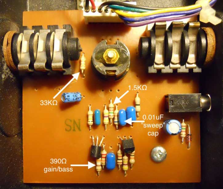
There are two places in the circuit where you can adjust the output level of the effect. To raise the level, either replace the 68K input resistor with a lower value (like 56 or 47K) or lower the value of the 390Ω resistor to something between 270-330Ω (which will also give the wah more bass). Remember that the Vox wahs use a 470Ω resistor instead of the Dunlop’s 390Ω, and it sounds just fine. If that makes the wah too quiet, you can counter it by lowering the 68K input resistor a little.
Vocal mod
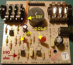
This is one of the earliest described wah mods. The 33K resistor in parallel with the inductor has a slight effect on the Q value (how sharp the resonance peak of the circuit is). Raising the resistor value makes the peak sharper (with a smaller ”Q” value), which in turn makes the ”wah” sound more like ”woh”. A sharper wah might more easily push a clean amp into distortion, though, so YMMV. I normally replace the 33K resistor with a 68K, since that was the value in many older Vox wah circuits, but feel free to experiment.
Note: be aware that changing this resistor only has a very slight effect – it is definitely not worth the effort to put a variable resistor (trimpot or regular potentiometer) in this position.
Lower range
The 0.01uF cap controls the frequency range. A lower value shifts the whole sweep higher in frequency, while a higher value lowers it. To shift the wah downwards (using more of the woofy bassy wah sounds), try a 0.015 or 0.022uF cap here. The JH-1 and Zack Wylde wahs has a 0.022uF here, instead of the 0.01uF in the GCB-95. Some Hendrix pedals also have two additional capacitors located right next to the adapter jack (on very old pedals, you may find one of them soldered across two of the pot legs). The bass wah (the old version with regular ”click” type footswitch, not the auto-on/off model) uses a 0.068uF cap instead of the 0.01uF in the regular GCB-95. (Thanks to Matt Parlane for providing the bass wah value.)
Mid control
The 1.5K resistor (located to the left of the 0.01uF capacitor) controls the shape of the midrange. A 1.8K to 2.2K resistor here will give you a bit more mids and a more pronounced peak. If you find that the wah becomes too pointy – for instance pushing a clean amp into distortion – sticking to the stock value or even lowering it to 1.2K might do the trick.
Fitting a replacement inductor (Rev E, F & G)
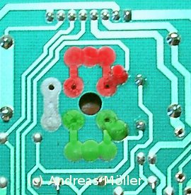
I find the stock Dunlop inductor to be adequate for most uses – the true bypass mod coupled with a few choice mods from the list above (particularly the vocal mod) will usually be enough for most people. But if you want to go further, or if you have a pedal that has a broken or particularly weak inductor (the mid-to-late ’80s Dunlops sometimes came with really shitty inductors), you can also replace it. There are plenty of options out there. Keep in mind that while the stock circuit board has many holes in this area, and the stock inductor (and a few replacements) has four connectors, only two really matter. Basically, there’s an ”upper” and a ”lower” group of holes – marked red and green in the pic to the right – and the inductor should go between any of the upper and any of the lower holes. If yours has four connections, you need to figure out what the pins do, so you can turn it the right way. Simply measure for resistance (using a multimeter) between the pins, and you should find the pins that are on either end of the coil. Sometimes, the two ”extra” pins aren’t connected anywhere (which the multimeter will show you), and other times, the pins are connected in pairs on either side of the coil.
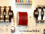
Here’s how a reissue Fasel inductor fits (works for both the red and yellow version) in a Rev F, G and H Crybaby. The Fasel inductor only has two connections, and will only fit in two specific holes, so it is quite easy to orient the right way. You may have to use desoldering braid first, to clear out the solder pads you want to use. The stock inductor was soldered to the four holes centered around the big hole, and this one fits into the two holes closest to the resistor. Make sure it sits flush with the circuit board – its legs are quite short.
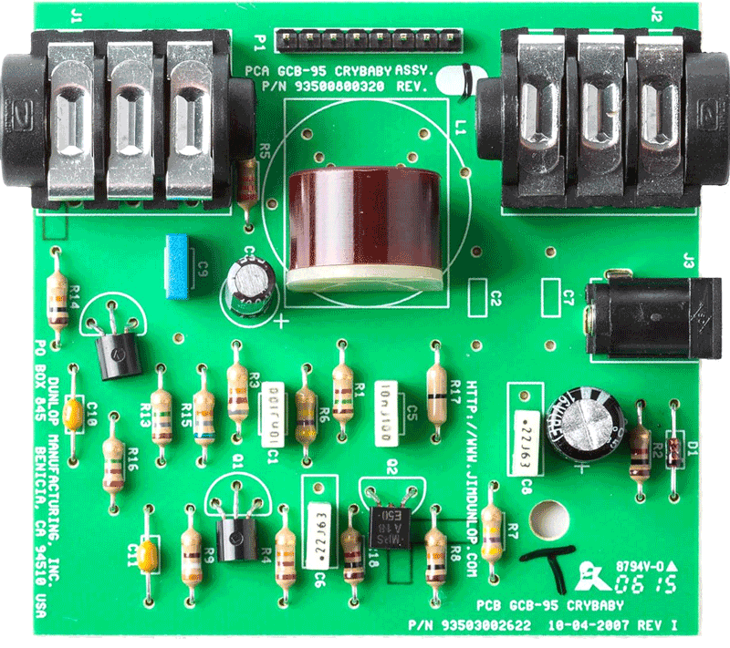
You can of course use this information to fit any inductor you like. As long as you keep track of which pins are the two main ones on the inductor, you should be able to match them to the picture shown earlier (so one pin goes to one of the red marked holes, and the other to one of the green ones). Also, the Revision I Crybaby model – pictured to the right – already comes with the red Fasel, and it also has a slightly different circuit board layout around the inductor. I haven’t gotten around to mapping that one out yet.
Modifying the Rev E Crybaby
If you have one of the older 1990-91 Revision E models, the circuit board layout is different from Revision F and onwards GCB-95’s. To the right is a picture of it, where I have marked out the components mentioned in the main part of the article. The notes should come out clearly, once you click on the picture to enlarge it.
I didn’t mark it out in the picture, but the 68K input resistor is sandwiched in between the 1.5K and 0.01uF ”sweep” capacitor. It’s not the most common one to change, but it’s good to know where it is.