This page assumes you have already done the true bypass mod, or plan to do it at the same time as this mod. Unless your pedal is one of the newest ones that come with a DPDT switch installed, there is no way to add an LED to the stock Crybaby without replacing the switch. Also, there is no real benefit to the stock bypass arrangement, so you might as well make it true bypass while you’re at it. Plus, some of the wire descriptions given later in this post will only make sense if you’re also doing the true bypass mod.
Finding power
So, how to add an LED? Well, while the simple answer is ”just steal 9v+ voltage from somewhere, add a current limiting resistor to the LED and switch it to ground when you want it to light”, it has proven to be a little more complicated. If you don’t do it right, you can introduce adapter noise into the signal, and/or get thumps when you turn the pedal (and the LED) on/off. So here’s how I do it…
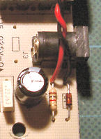
I only do this mod to pedals with adapter jacks incorporated into the circuit board (i.e. Rev E or later) – not because the LED draws that much power, but because those pedals also have polarity protection and extra filtering built in. The trick is to steal (and return) the power from outside the filtering, so that any thumps created when the LED lights up/shuts down will be eaten up by the filter capacitor, instead of being heard in the amp. The first step is therefore to locate the point where we will steal the voltage needed. On Rev F and later wahs, the positive and negative power can be found at the north end of the resistor and diode (respectively) that is located right below the adapter jack. From the resistor, run a wire to the anode (long) leg of the LED.
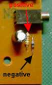
On Rev E wahs (pic to the right), the idea is the same, but the points are slightly different. The positive voltage point is still on the north side of the resistor (very close to the adapter jack this time, so be careful with the soldering iron), but the negative/ground point is now on the south leg of the diode.
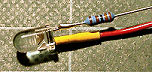
Solder the current limiting resistor to the cathode (short) leg, and connect it to the switch. The larger the resistor value, the less current the LED will use, which not only saves battery life but also minimizes the risk of getting switching noise due to the sudden current rush when the LED lights up or is turned off. Also, in extreme cases – if the resistor is too small – the current draw of the LED can starve the wah circuit to the point where you get lots of light, but no sound… With all that in mind, I use ultra-bright LED’s and 6.8-8.2K resistors (depending on the LED colour). Also, it is a good idea to cover the resistor to prevent it shorting out against something – I use shrink tubing. From the switch, run another wire back to the negative connection point by the adapter jack (north leg of the diode). That’s it!
Fitting the LED
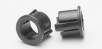
I usually drill out one of the two pre-punched holes in the case (inside, to the left and right of the switch), to fit the LED. Be careful, though – the drill will not fully clear the treadle, so when you have drilled through, it is very easy to nick the paint on the front lip of it. Also, you have to use a low profile LED holder (the plastic variety as shown to the right), as the treadle will not clear the larger chromed LED bezels. If you want to use one of those, you have to drill the hole from the top, so you know for sure it will clear the treadle.
Wiring the switch
The wire colours correspond to the wires in the Rev F and higher Crybaby wiring loom, but for the additional wires (circuit input, ground, +9v and 9v negative) you can obviously choose whatever colours you like. Again, I’m assuming you are also doing the true bypass mod, and have done the mods to the circuit board that comes with it. And if your pedal is a Rev E model, keep in mind that the green wire is the ”circuit input”, rather than ”main in”. For the LED, the side with the straight line corresponds to the cathode (short leg, with a flat side on the LED housing).
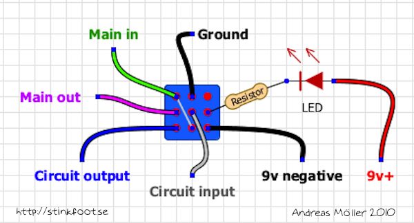
As the 3PDT is symmetrical (3×3 lugs), it is possible to accidentally turn it 90 degrees without noticing until you plug the pedal in and find out it doesn’t work. To make the switch line up with the diagram, make sure the holes line up north-south – imagine being able to thread a needle through all three lugs, and you should get it right.
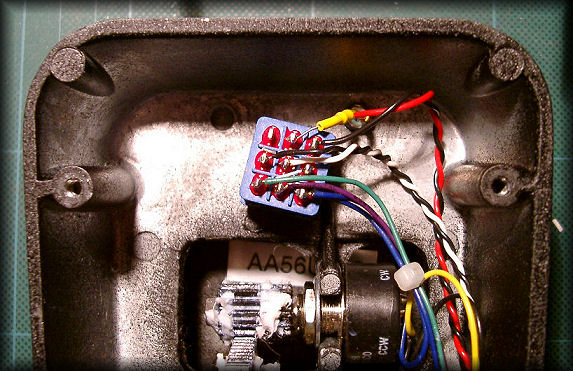
For reference, the pic below shows the top section of a GCB-95 with the LED installed and ready to go (click for closeup). Please note that this switch has been turned sideways, to make it clear the bracket that holds the pot. So to reference it to the diagram above, imagine turning the diagram almost 90 degrees to the left. Or – if you’d rather – imagine turning the picture to the right…
You could also use a Millennium-type LED control circuit, which will let you use a Carling DPDT and still get both true bypass and an LED. But that requires you to build a separate cirucit board for the LED circuit, and you also need to wire the switch a little differently. I might write a thing about that some day, but for now, I’ll stick with the 3PDT wiring.