This post deals with the newer Vox wah models. For a long time, Vox stuck to the circuit board layout of the ”old” Crybaby, and since there are already several sites out there that covers those, I haven’t bothered writing any instructions for them. Here’s a link to one of the best ones (go to ”DIY resources” and click the circuit board that matches yours), if you have an old Dunlop or Vox V846/847. However, Vox decided to outsource the production to China (Dunlop built the earlier models for them in the USA) and rather than go with the old simpler circuit, they added a whole bunch of components. Apparently they wanted to closer emulate an original ”Clyde McCoy” wah, and in doing so added – among other things – three small inductors in various parts of the circuit. They also included an adapter jack and the same buffer stage as found in the Dunlop GCB-95 (a quite sharp step away from the original ”Clyde McCoy”, circuit-wise). Sadly, they didn’t think it’d be a good idea to include true bypass in the upgrades, which would have made the buffer stage redundant…
Later, Vox introduced the V845, which turned out to be the same thing as the V847-A, but without the buffer stage. Still no true bypass, though… luckily, this guide works for both of them.
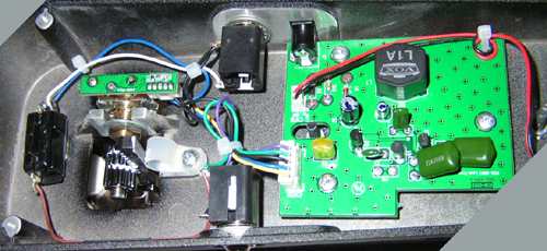
The pics used in this article were sent to me by a V847-A user who had found links to them in a review on Harmony Central. Of course, I’d love to give credit where credit’s due, so whoever you are – thanks! And of course, if you’d like a more thorough mention here, or if you’d like me to stop leeching and take my own damn pics, just let me know.
True bypass
Since Vox decided to keep the jacks separate from the circuit board, true bypassing it does not require any alterations to the circuit board traces. This makes the true bypass mod a fair bit simpler than on the Dunlop GCB-95 (and its siblings), which is nice.
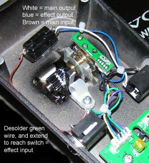
There are two wires coming off the input jack ”tip” connection – one reddish brown (I’ll just call it brown from now on) going to the switch, and one green going to the pcb. Desolder the green wire, while leaving the brown in place (you may have to resolder that one to the jack, but you get the drift). Add a ground wire – for instance to the ground tab on the input jack – and make sure it reaches the switch.
You now have all the connections needed, and can start removing the stock switch to install the new one. The wires are as follows:
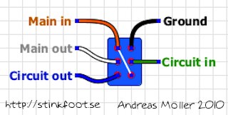
- Brown: main input
- White: main output
- Green: effect send/circuit input
- Blue: effect return/circuit output
- Black (or whatever colour your ground wire is): ground
The green wire will have to be extended to reach the switch, which is the only tricky part. I always use shrink tubing to cover the join – electrical tape can (and by Murphy’s law, will) come loose over time.
Taking out the buffer stage
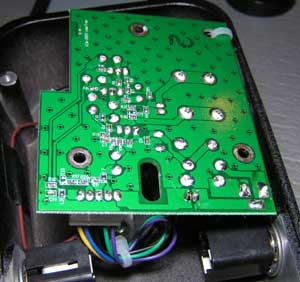
If the true bypass part was easy, getting the buffer out of the way will be a bit trickier. See the tiny surface-mounted components on the underside of the board? No? I don’t blame you – they are barely visible to the plain eye. Anyway, one of those is the input to the actual wah circuit, and attaching a wire to just one side of that resistor, without damaging anything, is not something I’d want to encourage people to attempt… I’d need to sit down with the pedal and trace everything out before I go further – once I’ve identified each component, it *should* be possible to remove the buffer stage and then use a hole vacated by one of the full-size buffer components to ”patch in” a new effect send/circuit input wire. But again, I’d need to have a sit-down with the pedal to make it happen. I have seen descriptions on the web, but I prefer to get hands-on before instructing others. If I get my hands on one, and decide it is a job that most people will be able to handle, I’ll do a full write-up and post it here.
Of course, the V845 doesn’t have the buffer stage, so for that one this is a moot point 🙂
Other mods
Due to the construction of the V847-A, with a lot of the components being the tiny surface-mounted (SMT) type, most of the usual mods will not be possible to do. At least not for people who don’t have serious soldering chops. Some of the mods are possible, though – as long as they involve normal-size components, anyone should be able to do the mods. Do take extra care desoldering, though – these holes are through-plated, with solder on both sides, so getting the components out can be tricky.
Again, more info will come when I’ve had the chance to work on one of these myself. From the looks of things, the vocal, midrange and gain mods will work as with the GCB-95, but as they all involve tiny surface-mount components, I don’t want to encourage DiY-ers to mess about with those (I get enough angry e-mails from people has damaged their pedals from poor soldering on regular-size components). Changing the sweep range will most likely be doable, as the 0.01uF ”sweep cap” is still a full-size component. The inductor is also possible to replace – I don’t know how the holes line up with the replacement inductors (reissue Fasel, Halo replicas or whathaveyou), but I can say that you don’t need to use all four holes. Only one in each horizontal ”row” (see above pic) is needed. Of course, I can’t say how much difference an inductor swap will make, considering the other three inductors in the circuit.
Also, manually altering the sweep by adjusting the pot axle’s position is of course still possible. See the GCB-95 circuit mods page for more info, if you don’t already know how to do it.
Adding an LED should also be possible, in much the same way as with the GCB-95. But again, let me get back to you on that subject.