Again, in the interest of lightening my work load, I’ve decided to post one of ”my” mods. The quotation marks are very justified in this case – the Tube Screamer mods I do can hardly be called innovative, and ideas on what can be done to a Tube Screamer are all over the internet. I just chose the values I liked the best, and gave the recipes names I thought appropriate (Stage 1 and 2). If you want to do it to yours, here’s how. Armed with the basic knowledge, you can of course choose your own values to create your own flavour.
The mods can also be applied directly to the reissue TS-808, as it has the same circuit board as the TS-9. But with that one, you obviously won’t have to do the TS-808 output section mod 🙂 The TS-9DX is partly the same, but some of the parts are located on a different circuit board. I still mod that pedal, as I feel I have something unique to offer there.
Stage 1 mod
This is the basic stuff – 808 output section, JRC4558D opamp (since 2006, TS-9’s already come with it) and a just a tad more low end response for a fuller tone. It’s not a dramatic change, but enough to make the pedal more useful.
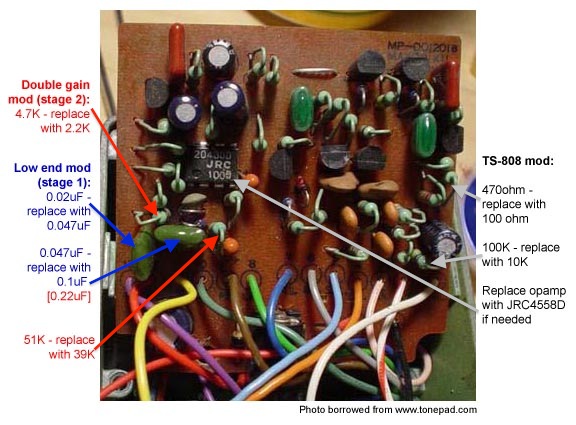
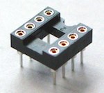
- Start with the 808 output section mod (outlined in black on the pic). If the pedal doesn’t already have the JRC4558D opamp, desolder the opamp and install the new one. Replacing the opamp makes a slight difference – not earth-shattering by any means, but enough to make it worth the effort. Use an IC socket – it’s much safer for the opamp, and makes it easy to try different ones.
- Then do the low end mod. The 0.047uF we take out controls the amount of low end going into the clipping section, and if you go too far with the value, things will get flubby. 0.1uF is just fine. The 0.02uF main input cap is a little too small for my taste, so replace it with a 0.047uF (you can re-use the one you took out earlier).
Stage 2 mod
This one has a little more hair on its chest – it comes with twice the gain, to push the pedal slightly into distortion territory.
- Again, start with the 808 output section mod, and replace the opamp if your pedal doesn’t already have a JRC4558D. Once again, use an IC socket instead of soldering directly to the new opamp.
- Then move on to the gain mods (in red in the pic). Replace the 4.7K resistor with a 2.2K, for twice the gain. The 52K resistor controls the amount of gain at the pot’s minimum setting, so replace it with a 39K to make the pedal clean up a little better.
- For the low end mod, take out both capacitors and replace the 0.02uF input capacitor with a 0.047uF as noted in the blue instructions. But instead of installing a 0.1uF cap in place of the 0.047uF, use a 0.22uF instead (noted in red). This capacitor works together with the gain resistor to roll off bass, and since you’ve just lowered the gain resistor, you have to raise the capacitor value accordingly.
Parts list
For the Stage 1 mod, you need:
- Resistors (1/4w): 100ohm, 10Kohm
- Capacitors (film type): 0.1uF, 0.047uF (the second is not needed if you re-use the stock 0.047uF cap)
- JRC4558D opamp and DIP8 IC socket (only needed if your pedal doesn’t already have the JRC4558D)
For the Stage 2 mod, the parts are:
- Resistors (1/4w): 100ohm, 10Kohm, 2.2Kohm, 39Kohm
- Capacitors (film type): 0.22uF, 0.047uF
- JRC4558D opamp and DIP8 IC socket (again, if your pedal doesn’t already have the JRC4558D)
Note that the Stage 2 mod also contained a compression switch, where one of the clipping diodes was replaced with a switch that selected one (stock clipping) or two diodes in series (asymmetric/Boss-style clipping). Personally, I found myself leaving the switch in the stock position (on the last pedal I did for myself, I didn’t even install the switch), so I’ve left it out of the mod description above.
Web resources
If you want to know all about how the tube screamer circuit works, look no further than this article by R.G. Keen. Also, take a look at this photoessay of the 808 mod from tonepad.com – it is very useful, as it shows the assembly and desoldering process. That essay is also where I borrowed the circuit board picture from 🙂