Do you have a pedal that isn’t found in the ”Power List”, and you want to know how much power it consumes? Assuming it is a battery-powered pedal, measuring it is easy – all you need is a multimeter, a 9v battery and a patch cable. And the pedal, of course. 🙂
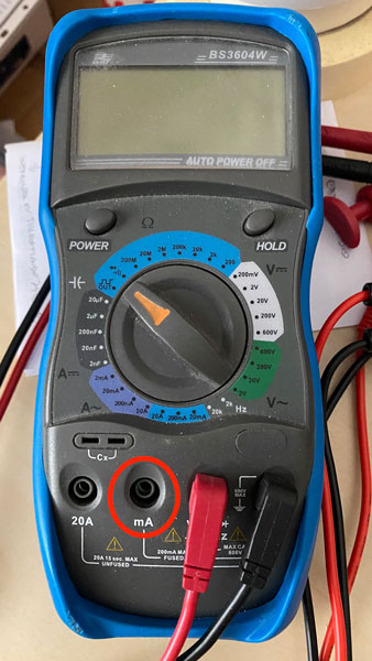
Set your multimeter to measure DC amperes (<200 mA or whatever suitable ”low” range your meter has). Don’t forget that on most multimeters you also need to move the red wire to a different connection on the meter. If you did forget, and wondered why nothing happened when you tried to measure the pedal, don’t fret – it happens all the time 😉
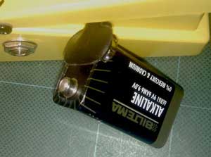
Then unplug the battery connector and put it back on sideways, so only the negative (-) pole is connected. Plug a cable into the input jack to make sure the pedal will be powered up, once you’ve completed the circuit.
Measure between the open battery pole and the open receptor in the connector. Use the multimeters’ red wire on the battery positive, and the black wire on the connector. The reading you get is the pedal’s current draw in resting/bypass mode. If it has an MXR-style mechanical switch, you can of course click the pedal on to get the ”active” mode current draw. In most cases, the pedal will draw a little more when active, so that’s the reading you want to go by.
If you want to get the ”active” reading on a pedal with electronic Boss/Ibanez type bypass, things get slightly more tricky. With the measuring probes still on the battery/receptor, click the switch to put the pedal in ”active” mode. The trick is to not let the measuring probes lose contact – that will cause the pedal to shut off, and when it receives power again, it will be back in ”bypass” mode. Of course, using alligator clips or the type of probe that can ”grab” things and hold on to them will make your life quite a bit easier here…
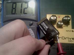
The giant hand (it’s not that big IRL, I promise!) is slightly obscuring the negative/black probe, but it is positioned on the connector in the battery clip. It’s pinched between my thumb and index finger, basically. I had to hold both probes in one hand to operate the camera with the other. Normally, you’d use one probe in each hand… You don’t have to input any signal, as most pedals draw full power as soon as they turn on. This particular pedal draws 8.12mA when active, and slightly less (just under 7mA) in bypass. Not a huge difference, thus, and I’d probably only report the higher figure, rounded up to 9mA.
Anyway – that’s it. Now go measure, and while you’re at it, help populate the list! Use the contact form below, or e-mail me directly if you prefer (address in the footer).
Wait – my pedal doesn’t run on a battery. What to do?
This one is a bit trickier, I must admit. The principle is the same – the multimeter needs to go inline with the power supply feed – but hacking it in is much more troublesome. Unless you are ready to cut your power supply cable apart, of course (please don’t). You can of course buy current meters – Truetone makes one specifically for this purpose. It won’t handle AC current (e.g. 9vAC), but for DC it works just fine. Personally, I made a special cable for this purpose. Basically, it has a female jack the adapter plugs into, and a male plug that plugs into the pedal. I’ve left one of the conductors open at the female end, which means I have a point to insert the multimeter. I left the positive/sleeve connection open, meaning one probe goes to the sleeve connection (in this case, the lowest soldering lug, as seen in the picture), and the other to the exposed wire. With that setup, you can of course just touch the first probe to the sleeve of the plug from the power supply, if you’d find that to be easier. Oh, and don’t forget to set the meter up to measure current/amperes – with most meters, you need to move the red wire to a different connection point to do this.

You need:
- 1 female 5.5×2.1mm jack
- 1 male 5.5×2.1mm or 5.5×2.5mm plug (the latter will fit pedals that use that size jack as well)
- A bit of 2-conductor cable (doesn’t have to be coaxial or shielded)
I’d suggest using a 2.1mm female jack/plug for plugging the power supply into, and a 2.5mm male plug for the pedal end. That way, the cable will work for both 2.1 and 2.5mm power supply plugs, as well as the jacks at the pedal end. Here’s a simple diagram to help visualize things:
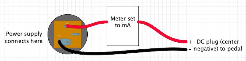
Um, that’s it. Keep track of which wire goes where (so you keep the center/sleeve configuration the same) and leave one wire open at one end. I used a female chassis jack, but you can just as well use a cable jack if you make sure the open wire is long enough to allow you to route it out through the plastic jacket. It doesn’t matter if you leave the center or sleeve wire open – if you get a negative mA reading, just flip the black and red multimeter probes. But if you do use a cable jack, it might be a good idea to leave the sleeve wire open. That way, you can put one probe on the sleeve itself (on the plug from the power supply) and the other on the exposed wire leading to the pedal.
Another option is to use cable jack/plugs – female 2.1mm at the start and male 2.5mm at the end – and just run a single wire from center to center on them. That completes the negative connection, and all you need to do then is to touch the sleeves (on the plug from the adapter and the plug going into the pedal, respetively) with the two multimeter probes. Assuming there’s enough of a gap there, with the plugs connected. It could be wise to ”try before you buy”, I guess.
Oh, and if your pedal runs on AC (9 volts AC, for instance – I’m not talking about wall/mains voltage here!), just set the multimeter to measure for AC amperes. The principle is otherwise the same.