This post is focused on how to modify the current production GCB-95 Crybaby for true bypass. It applies to all Dunlop wahs that use the GCB-95 circuit board, and that has the jacks mounted to said circuit board – in other words, the GCB-95 from 1990 onwards, the JH-1 (both the older ones and the new ”signature” model), the Zakk Wylde and the old GCB-100 bass wah. But let’s start with a little history:
History and background info
Before 1990, all Dunlop wah pedals had wires between the jacks and the pcb. In mid 1990 Dunlop changed the pcb design, and started soldering the jacks directly on to the circuit boards. The earlier type of pedal is quite easy to modify for true bypass, while the ones with circuit board-mounted jacks are a little harder. Also, from mid 1991 onwards, a buffer circuit was added before the actual wah circuit (it’s there if your pcb says ”Rev F” or higher on it), to help with some of the tone-sucking. The buffer is no longer needed if you mod the wah for true bypass, so it can (or dare I say ”should” :)) be removed. The current revision is Rev I, which has a different circuit layout around the inductor (which is the red Fasel reissue, btw). Other than that, it looks much like the Rev G and H wahs that has been running since mid 1992 (there is actually no real difference between G and H, other than the colour of the circuit board. Rev F, which appeared in 1991, had a different adapter jack, but that’s the only real difference between it and the G/H. Rev E units have a slightly different layout, and have a special section below.
Please note that I haven’t bothered to write any instructions for pedals that are older than Rev E (i.e. the pedals where the jacks aren’t mounted directly to the circuit board), as there are several other sites out there that already cover those. Here’s a link to one of the best ones (click ”DIY resources”, and then click the circuit board that matches yours). I do have a page on the newest Vox V847-A, though. There’s also a troubleshooting bit at the end, which may be helpful.
Important note: In these instructions I refer to ”upper”, ”lower”, ”north” and ”south”. You need to orient the pcb accordingly – the ”top” or ”north end” of the pcb is the one where the 8-pin connector is. And even though connections are made on the underside (trace/soldering side) of the pcb, directions like ”to the left of…” or ”just above…” refer to the front or component side of the pcb. Also, there are two different inputs being mentioned – in step 2 the ”input resistor”, and in step 2b the ”buffer input capacitor”. It is a little confusing, but the buffer circuit is a separate circuit that has been added on to the existing wah circuit. The buffer therefore has its input (the capacitor), which then feeds the wah circuit’s input (the input resistor).
Step 1: Disassembling the wah
Take the back plate off the wah by removing the 4 rubber feet and remove the battery. Unscrew the input/output jack nuts from the sides [tip: for Dunlop wahs, use a 7/16″ socket], then remove the 8-pin connector at the top of the pcb and the single screw that holds the pcb down. Now gently take the pcb out from the casing – it’s a tight fit, but it’ll come loose. Sliding it downwards (away from the pot) usually works for me.
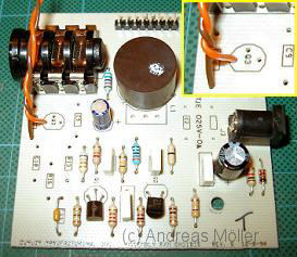
Now, find out what revision your pedal is. Later models (Rev H and I) have a written revision letter in the top right corner, while others have the revision identifier etched on the solder side of the board. You can also use the pictures, of course 🙂 The Rev E model (pcb-mounted jacks but no buffer) has its own section.
If your pedal is the earlier Rev E model, there’s a special section for it further below this bit. But we’ll start with the later models first. We will also be taking the input buffer stage out, as it was never part of the wah circuit to begin with, and serves no purpose once we’ve modified the pedal to true bypass. If you absolutely don’t want to remove it, there are special instructions for that further below.
Step 2: Mods to the pcb (Rev F, G, H & I)
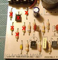
With the pcb out, take a good look at it and compare it to the one in the pics to the right. The buffer components are the ones crossed over with red X:s. It should be six components in all (including the transistor). You do not have to cut any traces – just remove these components, and you’ll be fine. Use a desoldering braid or a ”solder sucker” to remove the solder, and a pair of flat-nose pliers is also nice to have for quick and easy removal of components. Don’t jumper anything – just leave the holes as they are.
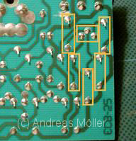
Cut yourself two pieces of wire (thin, flexible multi-strand type) that are long enough to easily reach the switch from the pcb. About 15 cm (6″) is a good length. Then carefully solder one of the wires in the far left hole (as seen from the component side) of the three vacated by the transistor. If you follow that trace you’ll see that it ends up on the north side of the 68K input resistor. This wire is your new effect input.
The other wire (which preferably should be of another colour than the first one) is a ground wire. You can connect it to any ground point, but the south hole vacated by the top left resistor is as good a place as any.
= Alternate to the above – skip straight to step 3 if you followed step 2 above =
Step 2b: Mods to the pcb [buffer stage kept intact] (Rev F, G, H & I)
As mentioned, I strongly recommend removing the buffer stage, as it was never part of the original wah circuit. But if you absolutely want to keep it (for instance if you don’t want to change the stock sound at all, only do the true bypass mod) here’s what you need to do.
With a sharp knife, carefully cut the trace between the input jack and the buffer input capacitor. This step can not be omitted – if you don’t cut the trace, the pedal will not be true bypass, regardless of the switch wiring. And with the way we will wire the switch, the bypass sound will be completely muted 🙂
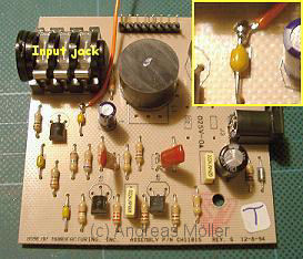
Again, you need a piece of wire (thin, flexible multi-strand) that is long enough to easily reach the switch from the pcb. About 15 cm (6″) is a good length. Then carefully solder the wire directly onto the north end of the buffer’s input cap. Slide the wire in under the capacitor’s leg, pull it as far back (away from the capacitor) as you can, and solder it in place. This wire is now your new effect input.
The ground wire mentioned in the above section still needs to be soldered somewhere. You can add it to any ground point in the pedal, or you can use the same technique as with the input wire and solder it to the south end of the top left resistor.
If the input capacitor in your pedal is the box type, you will have to make the connection on the solder side of the board instead.
= Special section only for 1990 pedals =
Step 2c: Rev E wahs (1990)
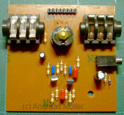
The first year the pcb mounted jacks appeared, the circuit was laid out differently compared to later models. If your pedal looks like the one in the pic (pcb colour may differ, but look at the component layout), it’s a Rev E pedal. You will need to cut a trace on this pcb (as there are no buffer components to remove), and we will also have to alter the wiring slightly. Instead of leaving the input jack -> 8-pin connector trace intact, we will break that connection and use the wire in the harness as the ”effect input” wire.
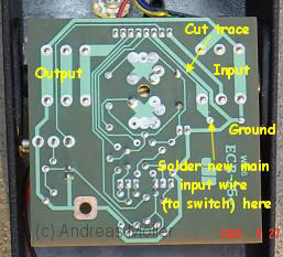
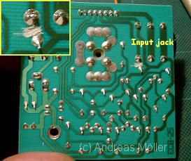
Cut the trace between the input jack and 8-pin connector. It is a fairly long trace, and you can cut it anywhere you like between the point where it becomes thin and where it meets the 8-pin connector. But be careful – it does sit a little close to its larger neigbour, so you can’t exactly use a hacksaw… When that is done, you need to cut a piece of wire about 15 cm (6″) long, and solder it to the pad right below the input jack (you may have to desolder the pad first). This is your new main input wire. The green wire in the 8-pin connector has now become the input to the circuit instead.
The ground wire can be soldered to the hole marked ”ground” in the pic. If that spot isn’t drilled out, or if you prefer not to run wires to the pcb, use the ground lug (where the black wire goes) on the potentiometer instead.
For the switch wiring detailed below, treat the green wire as the effect input, and the new wire you just added as the main input (i.e. the exact opposite of how you wire newer GCB-95’s). Thanks to Erik for the solder side pic!
Step 3: Wiring the switch
You need a good quality DPDT (double-pole, double-throw) switch. You can use any DPDT you like, as long as it will fit in the pedal. But keep in mind that it has to work with the treadle, so it can’t be too small. These days, I almost always use the Carling 316-B-PP DPDT switch. As it is the DPDT version of the stock switch, it will fit right in and ”feel” the same when you click the pedal over. For pedals that will get an LED as well, you need a 3PDT instead.
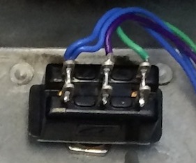
Update: I have recently (mid 2014) come across a few pedals of the latest revision (Rev I) that has come with a DPDT switch from the factory. They have been wired as SPDT switches, but could easily be rewired for true bypass. It could be that since more and more of the Dunlop signature wahs come with true bypass, they started using the DPDT’s for all pedals (it’s cheaper to buy larger quantities of the same part, after all). Or it’s just a temporary thing. Either way, take a look before you order any parts – if your switch looks like the one to the right, you already have the switch you need!
A DPDT switch consists of two SPDT switches side by side (if you bought a 3PDT, just ignore the third row of soldering lugs). The two halves (as marked in the graphic) are independent, but both center poles move in the same direction. This means that when switch A’s pole (#2) connects to throw 1, switch B’s pole (#5) connects to throw 4. Click the switch and pole 2 makes contact with throw 3 instead, while pole 5 connects to throw 6. Read this article by R.G. Keen if you want to indulge yourself in all things switching… The actual wiring of the switch is easy, if only a bit finnicky. It requres moderate soldering skills, but you’ll be fine. Just don’t warm the lugs too much – you can melt the switch if you are too slow. As with any soldering, be decisive and quick. Here goes:
- De-solder the connections on the old switch and remove it. Install the new DPDT switch and check that it fits and will work as intended. You should just barely be able to make it switch over when pressing the rocker pedal down by hand – using your foot and body weight will then compress the rubber stops enough to activate the switch. If you’re using a Carling switch, you can use the old switch as a guide to get a rough idea of how high to set the screw on the inside (the one that sets the switch height). Keep in mind that a Carling switch will have to sit horizontally across the top of the wah shell, so rotate the diagram 90 degrees to the left as well.
 Install a jumper wire between lugs 1 (top left) and 6 (bottom right) on the switch. Only solder lug 6 for now (tip: a cut-off leg from a resistor works great as jumper wire).
- Solder the existing wires from the wiring loom in place. The green (main input) wire to lug 1 [lug 5 for Rev E wahs], The purple (main output) to lug 2 and the blue (circuit output – can be one or two wires) to lug 3.
- Then solder the new circuit input wire you previously installed on the pcb to lug 5 [lug 1 for Rev E wahs], and the ground wire to lug 4.
- You’re done!
Troubleshooting
I’ve collected some of the more common problems (and their potential solutions) on the Wah mod FAQ page – check it out if you have a problem. Hopefully, it will lighten my e-mail load somewhat 🙂