This write-up is for the pre-1990 MXR pedals (Phase 90, Dynacomp etc). It is not for the later designs, where the jacks and switch are soldered directly to the circuit board. The principle is the same for those, but due to their design they’re much harder to mod (you’ll need to cut out a section of the circuit board, for instance). So before you start, verify that the jacks and switch in your pedal is the free-standing sort, with wires to/from them. The 1974 Handwired Phase 90 and 1976 Handwired Dynacomp will fall into this category, even though they’re made today.
The preparation
Start by identifying the inputs/outputs. The input jack will have two wires on the same solder tab – one leading to the circuit and another to the switch (this signal split is the tone-sucking thief we’re trying to eliminate, btw). The one leading to the switch is the main input, while the one leading to the circuit is the effect input.

The other two wires on the switch are the effect output and the main output, respectively. The main output will obviously lead to the output jack, so make note of which is which.
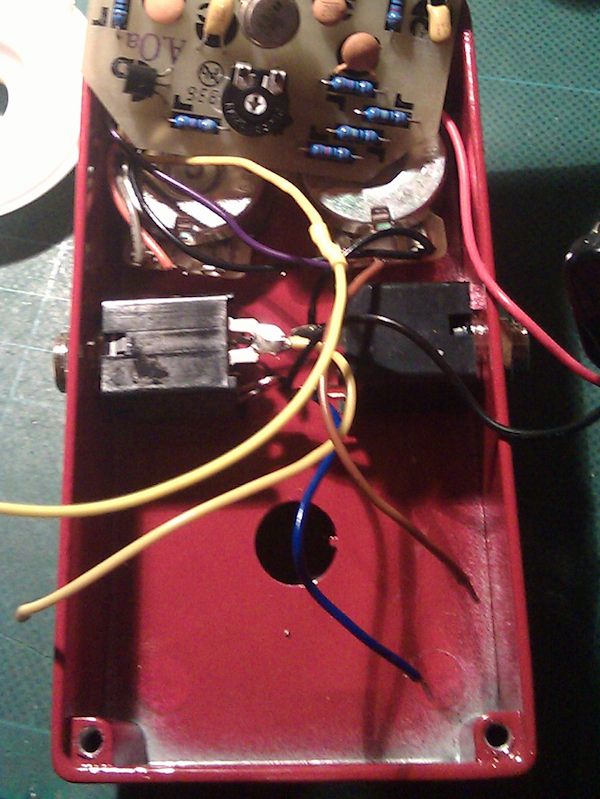
To the right, you’ll find a pic of the 1976 Handwired Dynacomp (click to enlarge). The two input wires (the one that feeds the circuit and the one that goes to the switch) are yellow, while the main output wire is blue. The brown wire is the output from the circuit.
Get to work:
- Desolder the effect input wire from the input jack (leave the shorter main input wire in place, as you’ll need it).
- Get a new wire to extend the effect input wire so it too can reach the switch.
- Then desolder all three wires from the switch and remove the stock switch. The pic to the right is taken at this stage.
- Add a new ground wire – solder it to the ground tab on one of the jacks, and make sure it will reach the switch location.
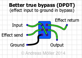
- Then simply follow any true bypass wiring diagram – you’ll find them here, from which page I’ve lifted the one below. The wire colours will obviously not match, but as long as you go by the wire descriptions, you’ll be fine.
You can also use this guide to do any old-style ”hardwire” bypass pedal – Ross, Coron, many of the pre-2002 EHX pedals etc. The principle is the same in them, although there may be differences in execution. For instance, in some pedals EHX used to run a wire from the input jack to the input point on the circuit board, and from there to the switch – in those, remove the jack -> circuit board wire and run a new main input wire between the jack and switch. The old circuit board -> switch wire then becomes the effect input.
The switch
You need a good quality DPDT (double-pole, double-throw) switch. You can use any DPDT you like, as long as it will fit in the pedal. You can also use a 3PDT if you like (you can use the third row of lugs to control an LED, or simply ignore it). Be aware that a ”blue” 3PDT will intrude slightly into the battery compartment, so fitting a battery will be hard work. It will work, but it’s a squeeze. The Carling 316 is the DPDT version of the stock switch, but you can use an Alpha, Alps or what have you – as long as it’s a latching (on-on) DPDT, it will work.
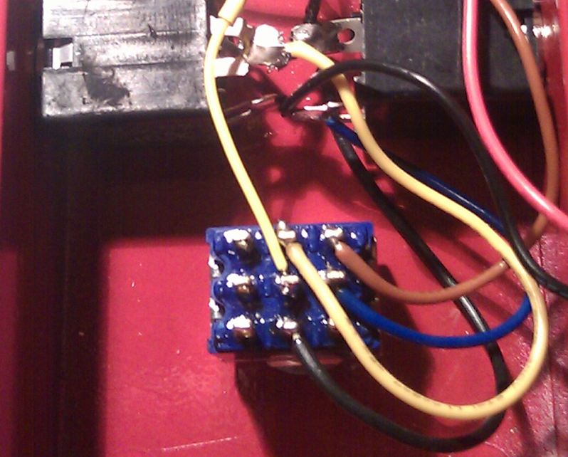
To the right, you’ll see what a 1976 Handwired Dynacomp looks like, fully wired up. I used a 3PDT here, but if you ignore the leftmost row of lugs, it’s the same as a DPDT. The yellow main input wire hides the jumper (the green line in the drawing above, from top left to bottom right), but it needs to be there, so don’t forget to put it in!
For now, I’m not going to do the LED option – it’s a much more complicated operation, as you have to steal power and drill into the case. Also, I wire my true bypass switches with input grounding, to avoid crosstalk (when the effect can be heard faintly even in bypass mode) and switching pops. This is the reason we added a ground wire earlier – if you plan on using the simpler wiring style (where the bottom two lugs are connected to form a bridge between input and output in bypass mode), you won’t need the ground wire.