As mentioned in the ”ACA vs PSA” post, some of the older Boss pedals (those with an ”ACA” sticker by the adapter jack) won’t work right with a normal 9vDC power supply. Keeping them on a daisy chain supply, with power and signal cables connected to at least one normal (PSA) pedal makes them light up, but in all other instances they need 12 volts DC on the adapter jack. Thankfully, it is quite easy to modify these pedals to accept normal 9vDC power, so you no longer have to think about it. In this post, we’ll learn how.
But first, a little theory…

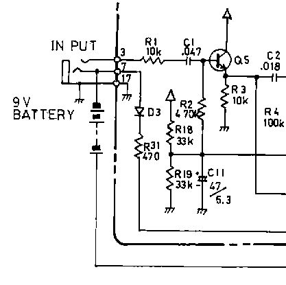
Before we start, I thought it’d be a good idea to look more into why these pedals work fine from a 9v battery, but need 12 volts on the adapter jack. Let’s use the SD-1 as an example, and peek at the schematic to the right, showing the input section and battery connection. D3 and R31 are the culprits (the component numbers are different in other Boss ACA-spec pedals, but their positions in the schematic are the same). They sit between the adapter jack negative (outside the schematic portion pictured) and the input jack’s ”ring” connection. What this means is that while the battery negative goes straight to ground (when there’s a mono plug in the input jack), the adapter jack’s negative runs through those components before it hits ground.
The mod
There are two ways to do this mod. One way is to connect the adapter jack negative (usually a blue wire) to the wire going to the input jack ”ring” terminal. Simply moving a wire seems to be the easiest way, but the way Boss soldered the wires to some of these old pedals can actually make it quite messy. So we’re going to do it properly, the way Boss themselves do it… again, the SD-1 will serve as the guinea pig:


Desolder and remove the diode (D3) and resistor (R31). If the pedal is valuable/collectable, I usually tape the components to the inside of the box, so they can be replaced if need be. In their place, install and solder jumpers (cut-off resistor legs work fine).

That’s it! Keep in mind that the pedal is now PSA-spec, so don’t feed it 12 volts unless you know it can handle the additional voltage.
Other pedals
In this article we used the SD-1 as an example, but there are other Boss ACA pedals out there. If you can find the schematic for your particular pedal (google for ”service notes”), you should be able to find out the specific component numbers for it. The service notes also often have a drawing of where each component is on the circuit board, which is really useful as some of the older ones don’t have component labels drawn on the circuit board itself. Below, I’ve listed the ones I know. In some pedals, the resistor isn’t numbered even in the schematic. I’ve noted the value for those, but then you’ll have to do a little detective work yourself (tip: the resistor will be connected to one side of the diode).
- BF-2: D10/R64
- CE-2, CE-2B: D5/R53
- CE-3: D1/R1
- CS-1: D4/470Ω
- CS-2: D2/R38
- CS-3: D10/R32
- DF-2: D1/R5
- DM-2: D1/R2
- DM-3: D1/R3
- DS-1: D3/R38
- FT-2: D2/R4 (on the main circuit board)
- GE-7/GE-7B: D1/R1
- HF-2: D10/R64
- HM-2: D1/R2
- LM-2: D2/R2
- NF-1: D4/470Ω
- OC-2: D3/R17
- OD-1: – D4/R30
- OD-2: D1/R2
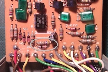
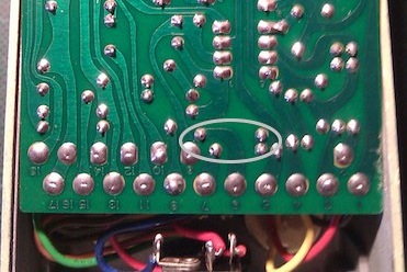
- PH-1: D5/R45 (390Ω) (see the PH-1 circuit board here with the components circled. Before you do any surgery, verify that the resistor in your pedal starts out at point 6 on the board, connects to the diode which in turn ends up at point 10.)
- PH-1r: D6/R56
- PH-2: D5/R9
- SD-1: D3/R31
- SG-1: D4/R38
- SP-1: D4/R30
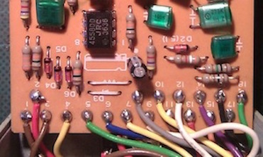
- TW-1: D8/R48 (470Ω right below D8 – if you have one of the early ones that have an unmarked pcb, here’s the TW-1 circuit board with the components circled)
- VB-2: D1/R1