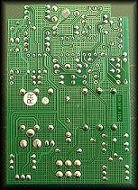
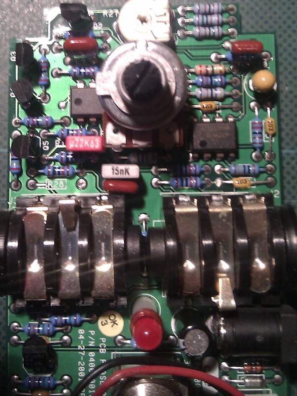
This post deals with the regular MXR Phase 90 (M-101), Revision E and F. It does not apply to the EVH phaser, Custom Shop Script models (with and without LED), as they have a different type of circuit board. The 1974 Handwired model can be true bypassed with the help of this post. But for this excercise, make sure the circuit board in your matches the one pictured to the right – some boards are green and others red, but as long as the layout is the same, it’ll work. It will say ”Revision E” or ”Revision F” somewhere on the circuit board (either on the solder side, as shown here, or on the component side).
Also, I’ve noted the difficulty level for each mod. Be advised that desoldering components from the M-101 circuit board is tricky – it has through-plated holes, and it is very easy to damage the board. I do not offer support or troubleshooting help, nor am I liable for any damaged pedals.
Before we start, I should also say something about the trimpot. The M-101 Phase 90 does have one, located at the top of the board. Do not adjust it – you will just make the pedal not function properly. Despite popular belief, it is not an effect mix or intensity setting. It is used by the factory to compensate for component tolerances, to make the oscillator work properly. If the pedal works, the trimpot is set where it should be. If it’s set anywhere else, there will be no phase effect…
R28 mod (also known as the ”script” mod)
Difficulty: simple
The regular Phase 90 has a feedback resistor – basically, some of the phased signal is fed back into the phaser section, to make the effect stronger and more pronounced. However, it also causes some distortion in the midrange, which isn’t very pleasant. Cutting the feedback resistor out makes the effect more mellow, making the pedal sound a little more like the original ”script logo” pedals from the ’70s. This mod is part of the Stinkfoot Stage 1 Phase 90 mod, by the way. You can hear the difference here:
M-101 Phase 90 (clean, then stock pedal)
M-101 Phase 90 (R28 modified)
All you need to do this mod is the tools needed to disassemble the pedal and a pair of cutting pliers. No soldering needed!
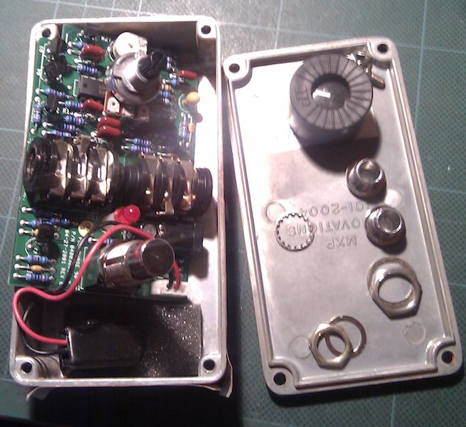
Start by disassembling the pedal – remove the knob (on most pedals, it simply pulls straight off the shaft) and the jack nuts. Then remove the nuts holding the pot and switch in place. Gently push on the pot and switch, and the circuit board should pop out of the box. Make sure to note where washers etc goes, so you can put it all back together again.
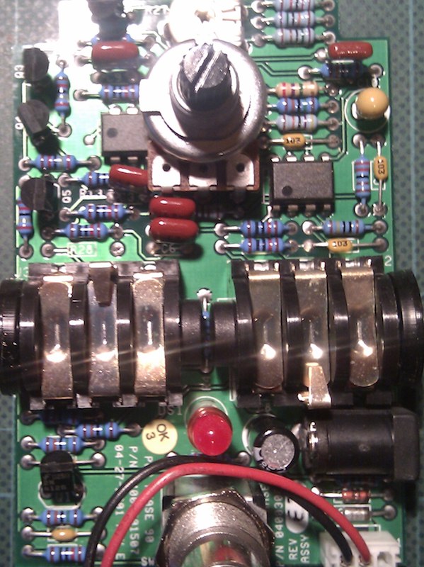
Then locate R28 (right above the output jack) and clip one end off. You can clip the resistor out at both ends if you like, or just cut one end and raise it enough to break the connection. Do not desolder the resistor! I can not stress this enough – one of the through-plated holes also serves as a pathway between the two sides of the circuit board, and it is very easy to damage it (leaving you with a dead pedal). A pair of small cutting pliers is all you need, and will keep the pedal safe and working fine.
Then simply put the pedal back together. Don’t forget the washer that goes on the pot (inside the box) – without it, the circuit board won’t sit right. Once I have the board back in the box, I always start with the nuts for the jacks. Do them up by hand first, to make sure you don’t damage the threads in the plastic jacks.
Univibe mod
Difficulty: medium
This is a mod to the phasing section which makes the phaser a little more wobbly (more like a Uni-vibe – hence the name). A Uni-Vibe is at heart a four-stage phaser, just like the Phase 90. The main differences are that the Uni-Vibe uses a lamp/photocell circuit to produce the sweep, and the capacitor values for the phase stages. I initially tried replacing all four capacitors with the values from the Uni-Vibe, but eventually settled on replacing only two of them. Together with the R28 mod above, it was part of the Stinkfoot Stage 2 Phase 90 mod. You can hear it here:
M-101 Phase 90 (R28 and Univibe mod)
This mod is a little more involved, as it requires you to desolder two capacitors, clean up the holes (without damaging them) and install new ones. This time, you need a soldering iron/station with a fairly small tip, solder and a desoldering braid.
Start by disassembling the pedal, as described above.

Locate C1 and C3, desolder and remove them. Use desoldering braid to make sure you’ve cleaned up the holes as much as possible before removing the capacitors. Keep in mind that the holes are through-plated, so there will be solder on both sides of the board. I use the soldering iron to heat the soldering point from the back, and lift the legs of the capacitor straight up. After clearing as much of the solder as possible with a desoldering braid, I then push the capacitor legs through with the tip of the soldering iron. To clean the holes up, I sometimes add fresh solder and desolder it again.
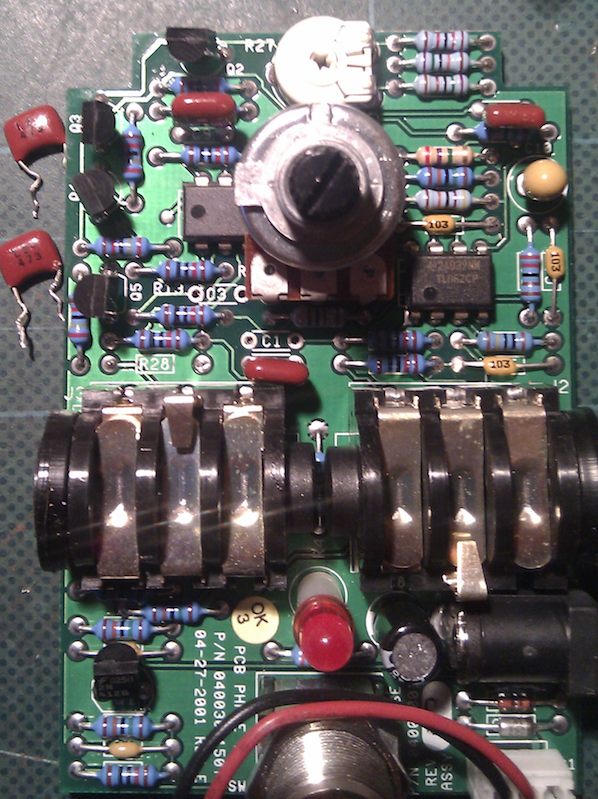
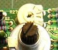
What you’re left with should look like the picture to the right. Once you’re there, install the new capacitors:
- C1 = 0.015uF
- C3 = 0.22uF
Use box film capacitors with 5mm spacing – caps with bigger physical size will be tricky to fit, due to the proximity of other parts.
Put the pedal back together, as described earlier.
That’s it! And before you ask – yes, the Revision E Phase 90 can be modified to true bypass as well. But on pedals with this type of setup (where the switch is soldered directly to the circuit board, it is quite advanced work, requiring you to cut out a section of the board and cut tiny circuit traces. On that basis, I am a little hesitant to provide such information, as I already get enough angry e-mails from people who have messed their (simpler) mods up. It’s funny how some people can do a hack job, and then accuse me of ”damaging their pedal”, wondering ”what I am going to do about it”…
Basically, I figure that if you’re proficient enough to do such work without damaging the circuit board, you’re also proficient enough to figure out the input/output points yourself 🙂
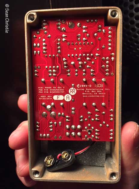
Update february 2018: I was just sent an image of a Revision F M101, which looks to be true bypass. It has roughly the same circuit as the Revision E model featured in this article, but with a few small changes at the lower end of the circuit board, around the footswitch and associated bits (the addition of a Millennium-style LED control, among other things). Unlike the (apparently transitional) M101’s I’ve seen that used the EVH/Custom Shop Script circuit board, this one still uses regular through-hole components. I haven’t seen this circuit in the flesh, but from what I have seen, I expect the mods described above to work the same on this one as on the Revision E.
Thanks to Sean Christie for the heads-up, and the image of the Rev F Phase 90!